
 +86 183 5026 5271



Energy Management System
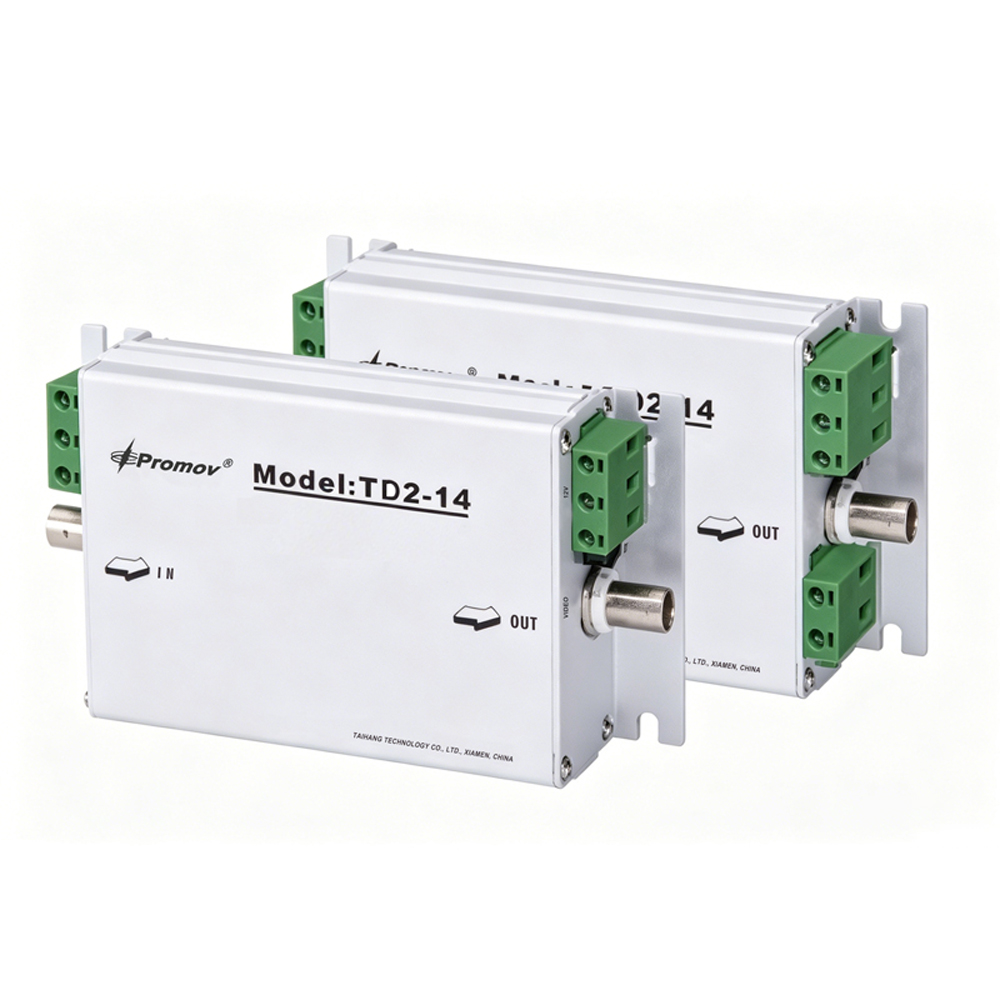
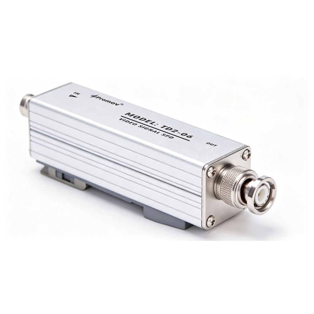
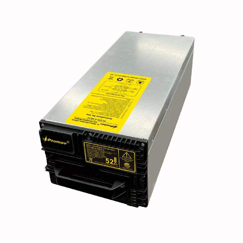
2.5kWh semi-solid-state pluggable battery
Product Features
Battery features self-protection against high temperature and water ingress,with no fire risk.
Reliable
● Plug-and-play design for easy installation, replacement and emergency swap between sites.
● High-safety LFP solid-state battery with excellent safety performance; passes overcharge, over-discharge, short-circuit, extrusion, acupuncture, drop and heating tests without fire, explosion or leakage.
● Intelligent BMS system provides full protection including over-voltage, under-voltage, over-current, short-circuit, over-temperature and low-temperature protection.
● Cell voltage balancing ensures consistent performance and extends service life.
● Ultra-fast short-circuit protection (800A, 50μs response) for high security.
● Long cycle life: ≥3600 cycles with capacity remaining above 80%.
● Real-time SOC indication via LED indicator for clear battery status.
● Wide operating temperature range: charging 0°C~+55°C, discharging -20°C~+60°C.
● High-temperature insulated cotton & flame-retardant sponge for thermal insulation, shock absorption and anti-vibration.
● 6-channel temperature sensors monitor cell temperature in real time.
● High-current 8AWG silicone cable with high temperature resistance and aging resistance.
● RS485 communication (9600 bps) for remote monitoring and data reporting.
● Natural cooling, maintenance-free for stable outdoor operation.
Scope of Application
This plug-and-play solid-state battery module is mainly designed for outdoor communication base stations, intelligent outdoor integrated cabinets, energy storage systems, and backup power supplies.
It is widely used in scenarios requiring high safety, long service life, and convenient maintenance, such as:
● Outdoor communication base stations (4G/5G)
● Integrated energy storage & UPS power supply systems
● Outdoor intelligent power cabinets
● Peak shaving and valley filling systems
● Industrial & commercial backup power
● Harsh outdoor environments with wide temperature changes
Technical Specifications
Cell Parameters
Item |
Specification |
Material Type |
Lithium Iron Phosphate (LFP) |
Nominal Voltage |
3.2V |
Cell Capacity |
≥53Ah |
Operating Voltage Window |
2.5–3.65V (T>0℃)2.0–3.65V (T≤0℃) |
Max. Charge Current |
1C |
Max. Continuous Discharge Current |
3C (at 25℃) |
ACR |
<1mΩ |
BMS Parameters (Configurable)
Item |
Specification |
Balancing Start Voltage |
3.4V |
Balancing Start Voltage Difference |
0.04V |
Balancing Current |
100mA |
Over-charge Protection Voltage |
3650mV |
Over-charge Protection Delay |
2S |
Over-charge Recovery Voltage |
3550mV |
Over-charge Recovery Delay |
2S |
Over-charge Recovery Condition |
Each cell voltage < recovery voltage |
Pack Over-charge Protection Voltage |
54V |
Pack Over-charge Protection Delay |
2S |
Pack Over-charge Recovery Voltage |
53V |
Pack Over-charge Recovery Delay |
2S |
Software Charge Over-current Protection |
55A |
Charge Over-current Delay |
2S |
Charge Over-current Recovery Delay |
2S |
Over-discharge Protection Voltage |
2.5V (T>0℃)2.0V (T≤0℃) |
Over-discharge Protection Delay |
2S |
Over-discharge Recovery Voltage |
2.65V |
Over-discharge Recovery Delay |
2S |
Over-discharge Recovery Condition |
Each cell voltage > recovery voltage after load off |
Discharge Over-current 1 |
55A / 2S |
Discharge Over-current 1 Recovery |
2S |
Discharge Over-current 2 |
65A / 0.5S |
Discharge Over-current 2 Recovery |
4S |
Short-circuit Protection Current |
800A |
Short-circuit Protection Delay |
50μs |
Short-circuit Recovery Delay |
30S |
Charge High Temp. Protection |
55℃ |
Charge High Temp. Recovery |
50℃ |
Charge Low Temp. Protection |
0℃ |
Charge Low Temp. Recovery |
5℃ |
Discharge High Temp. Protection |
60℃ |
Discharge High Temp. Recovery |
50℃ |
Discharge Low Temp. Protection |
-20℃ |
Discharge Low Temp. Recovery |
-15℃ |
MOS Over-temperature Protection |
90℃ |
MOS Over-temperature Recovery |
60℃ |
Communication |
RS485, 9600bps |
Terminal & Cable Rating |
60A MAX (at 25℃) |
LED Indication (SOC)
LED Status |
SOC Range |
Red + 4 Blue ON |
80% < SOC |
Red + 3 Blue ON |
60% < SOC ≤ 80% |
Red + 2 Blue ON |
40% < SOC ≤ 60% |
Red + 1 Blue ON |
20% < SOC ≤ 40% |
Red ON, Blue OFF |
5% < SOC ≤ 20% |
Red Blinking, Blue OFF |
SOC ≤ 5% |
battery Introduction
This is a plug and play solid state lithium iron phosphate (LFP) battery module designed for outdoor energy storage, communication base stations, and integrated power cabinets. It adopts high safety LFP chemistry with 15 series cells, providing 48V / 52Ah stable output and long cycle life up to 3,600 cycles.
The module supports hot swap for easy installation and replacement, and is equipped with a high performance BMS that provides full protection including over voltage, under voltage, over current, short circuit, over temperature, and low temperature protection. It features real time SOC indication via front LED indicators, RS485 communication for remote monitoring, and natural cooling for maintenance free operation.
With a wide operating temperature range from 20℃ to 60℃, high temperature resistance, flame retardant materials, and 6 channel temperature monitoring, the battery ensures high safety, strong adaptability, and stable performance in harsh outdoor environments.
Basic Circuit Diagram
Dimensions
Overall Dimensions (mm)
● Main cabinet outline: 658 × 624 × 1460 mm
● Alternative cabinet size: 844 × 760 × 1567 mm
Battery Module Dimensions (mm)
● Single battery pack: 540 × 200 × 150 mm
Height Definition
● Cabinet height (Type A): 1.8 meters (1800 mm)
Installation Instructions
Certificate
Document Download
Quality Inspection(Test reference)
1 Inspection Reference
IEC61643.11 Surge Protective Devices (SPD) for Low-Voltage Distribution Systems
Part 1: Performance Requirements and Test Methods
GB/T 2828.1-2012 Sampling Inspection Procedures
Part 1: Sampling Plans for Inspection by Acceptance Quality Limit (AQL)
2 Incoming Inspection
Incoming material inspection is conducted based on the "Metal Parts Inspection Standard," "Plastic Parts Inspection Standard," "Electronic Parts Inspection Standard," "Auxiliary Materials Inspection Standard," and the GB/T 2828.1-2012 Sampling Inspection Procedure.
3 Finished Products Inspection
1) Routine test
Routine inspection is a 100% inspection conducted at the final stage of production on products from the production line. After inspection, no further processing is done, except for packaging and labeling.
2) Sampling test
Sampling inspection is performed according to the GB/T 2828.1 sampling standard.
3) Acceptance test
Verification inspection is a sampling inspection conducted to ensure that the product continues to meet the standard requirements. Verification inspection should be carried out according to the procedures and frequency specified by the standard.
Inspection Table
|
Inspection Items |
Routine test |
Sampling test |
Acceptance test |
|
Packaging |
|
√ |
|
|
Appearance Quality |
√ |
√ |
√ |
|
Structure and Shape |
√ |
||
|
Remote Signal Alarm Function |
√ |
√ |
√ |
|
U1mA Value Test |
√ |
√ |
|
|
Markings and Labels |
√ |
√ |
√ |
|
Direct Contact Protection Test |
√ |
||
|
Standby Power Consumption and Residual Current |
√ |
||
|
Protection Level |
√ |
||
|
Action Load Test |
√ |
||
|
Thermal Stability Test |
√ |
√ |
|
|
Temporary Overvoltage (TOV) Test |
√ |
||
|
Mechanical Strength |
√ |
||
|
Insulation Resistance |
√ |
||
|
Dielectric Strength |
√ |
||
|
Environment, IP Code |
√ |
||
|
Electrical Clearance and Creepage Distance |
√ |
||
|
Resistance to Abnormal Heat and Flammability |
√ |
||
|
Status Indicator Operation |
√ |
√ |
√ |
|
Isolation Between Separate Circuits |
√ |
||
|
Transportation Vibration Test |
√ |
||
|
Free Fall Test |
√ |
||
|
Insertion and Withdrawal Force Test Before Surge Impulse (for Pluggable Modules) |
√ |
√ |