
 +86 183 5026 5271



Smart Lightning Monitoring &Warning System
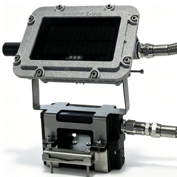
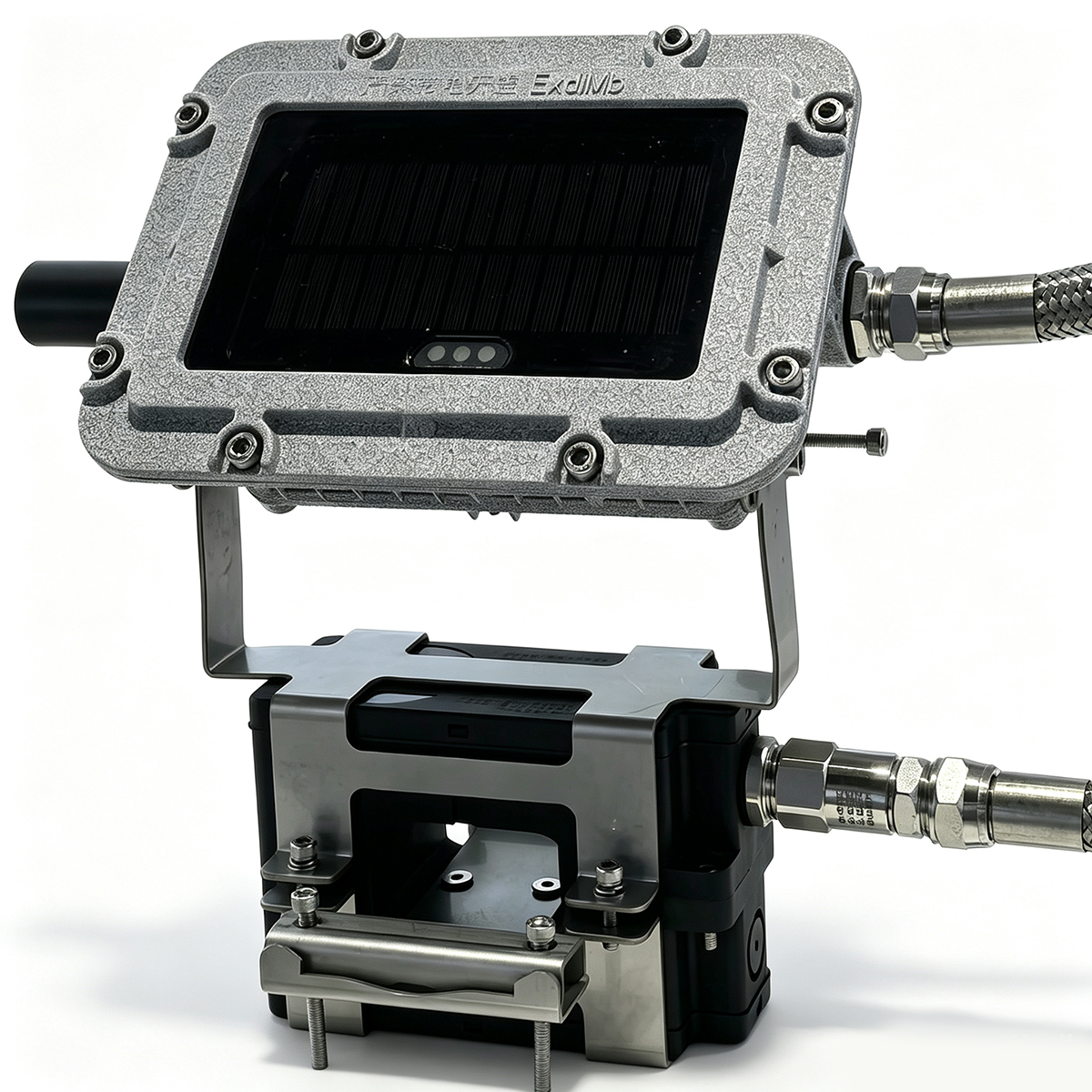
TJ1 Online Ground Resistance Monitoring Device
Product Features
● Online non-contact measurement, supports networking multiple devices, real-time data upload.
● Implement functions for historical data storage, querying, statistics, and analysis.
● Hinged structure installation; no need to disconnect the grounding wire. The wire passes through the core without affecting lightning protection, making it convenient and quick.
● Wired and wireless communication methods, with antenna transmission power less than 30 dBm.
● Features lightning peak recording function, real-time recording of lightning peak values and occurrence times.
● The product meets Zone 1 explosion-proof classification, with explosion-proof marking Ex db mb IIC T6 Gb.
Scope of Application
The basic principle of the TJ1 ground resistance online monitor is to measure the loop resistance. The sensor first applies an excitation pulse signal to the ground loop under test. This generates an induced pulse potential E on the loop. Under the action of this potential E, a current I is produced in the loop. The sensor measures both E and I, and the loop resistance is then calculated using the formula R = E/I.
Technical Specifications
| Model | TJ1-A | TJ1-B |
| Power supply | 5VDC (Solar panel + battery) | 12~24VDC |
| Measurement method | Circuit method | Circuit method |
| Impedance range | 0.10Ω ~ 100.00Ω | 0.10Ω ~ 100.00Ω |
| Resolution | 0.01Ω | 0.01Ω |
| Accuracy | 0.10~0.99Ω : ± ( 1%+0.10Ω )1.00~49.90Ω : ± ( 1.5%+0.10Ω )50.00~100.00Ω : ± ( 2%+0.50Ω )(20℃±5℃, <70%RH) | 0.10~0.99Ω : ± ( 1%+0.10Ω )1.00~49.90Ω : ± ( 1.5%+0.10Ω )50.00~100.00Ω : ± ( 2%+0.50Ω )(20℃±5℃, <70%RH) |
| Range for setting automatic monitoring interval | 1 ~ 999hour | 1 ~ 999hour |
| Test duration | 30s/per Max | 30s/per Max |
| Communication method | 4G | RS485 |
| Data display | System software display | System software display |
| Operating temperature and humidity | -30℃~55℃ ; 5% ~ 95%RH | -30℃~55℃ ; 5% ~ 95%RH |
| Storage temperature and humidity | -30℃~60℃ ; 5% ~ 95%RH | -30℃~60℃ ; 5% ~ 95%RH |
| Electromagnetic characteristics | IEC61010-4-3 , Wireless frequency electromagnetic field ≤ 1 V/m | IEC61010-4-3 , Wireless frequency electromagnetic field ≤ 1 V/m |
| Insulation resistance | Above 10 MΩ (between circuit and enclosure, 500V) | Above 10 MΩ (between circuit and enclosure, 500V) |
| Enclosure protection rating | IP66 | IP66 |
| Explosion-proof rating | Ex db mb IIC T6 Gb | Ex db mb IIC T6 Gb |
| Corrosion resistance rating | WF2 | WF2 |
Additional Features
Lightning peak recording |
Recording Range: 1~100 kA (10/350μs)Measurement Accuracy: ±(20% + 0.5 kA) (20℃ ± 5℃, < 70% RH)Data Storage: 0-99 records including resistance value, resistance measurement time, lightning peak current, and lightning occurrence time |
Basic Circuit Diagram
Dimensions
Certificate
Document Download
Quality Inspection(Test reference)
1 Inspection Reference
IEC61643.11 Surge Protective Devices (SPD) for Low-Voltage Distribution Systems
Part 1: Performance Requirements and Test Methods
GB/T 2828.1-2012 Sampling Inspection Procedures
Part 1: Sampling Plans for Inspection by Acceptance Quality Limit (AQL)
2 Incoming Inspection
Incoming material inspection is conducted based on the "Metal Parts Inspection Standard," "Plastic Parts Inspection Standard," "Electronic Parts Inspection Standard," "Auxiliary Materials Inspection Standard," and the GB/T 2828.1-2012 Sampling Inspection Procedure.
3 Finished Products Inspection
1) Routine test
Routine inspection is a 100% inspection conducted at the final stage of production on products from the production line. After inspection, no further processing is done, except for packaging and labeling.
2) Sampling test
Sampling inspection is performed according to the GB/T 2828.1 sampling standard.
3) Acceptance test
Verification inspection is a sampling inspection conducted to ensure that the product continues to meet the standard requirements. Verification inspection should be carried out according to the procedures and frequency specified by the standard.
Inspection Table
|
Inspection Items |
Routine test |
Sampling test |
Acceptance test |
|
Packaging |
|
√ |
|
|
Appearance Quality |
√ |
√ |
√ |
|
Structure and Shape |
√ |
||
|
Remote Signal Alarm Function |
√ |
√ |
√ |
|
U1mA Value Test |
√ |
√ |
|
|
Markings and Labels |
√ |
√ |
√ |
|
Direct Contact Protection Test |
√ |
||
|
Standby Power Consumption and Residual Current |
√ |
||
|
Protection Level |
√ |
||
|
Action Load Test |
√ |
||
|
Thermal Stability Test |
√ |
√ |
|
|
Temporary Overvoltage (TOV) Test |
√ |
||
|
Mechanical Strength |
√ |
||
|
Insulation Resistance |
√ |
||
|
Dielectric Strength |
√ |
||
|
Environment, IP Code |
√ |
||
|
Electrical Clearance and Creepage Distance |
√ |
||
|
Resistance to Abnormal Heat and Flammability |
√ |
||
|
Status Indicator Operation |
√ |
√ |
√ |
|
Isolation Between Separate Circuits |
√ |
||
|
Transportation Vibration Test |
√ |
||
|
Free Fall Test |
√ |
||
|
Insertion and Withdrawal Force Test Before Surge Impulse (for Pluggable Modules) |
√ |
√ |